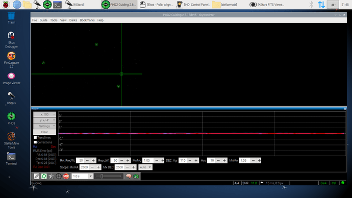
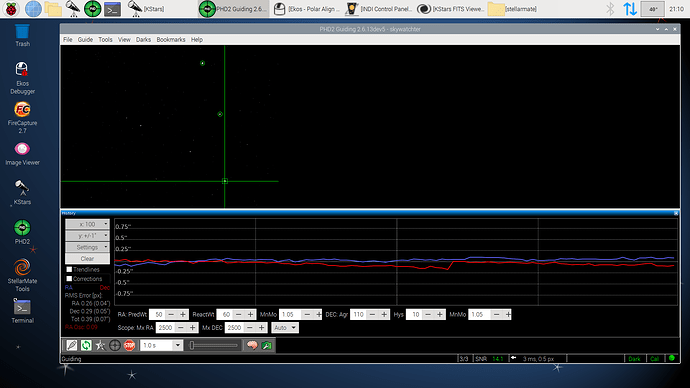
The new Harmonic Drive (HD) or strain wave gear (SWG) mounts (strain wave gear, Harmonic Drive – Wikipedia (Strain wave gearing - Wikipedia) are currently very popular. They are very light weight and need no balancing of the OTA, which makes them easy to transport. A reason why I bought a WarpAstron WD-20 mount by myself. 30 kg less weight for my 10”/ f4.5 (F=1200mm) Newton system to carry up and down a narrow staircase is a great help.
Starting with the classic approach on my autoguiding parameters, I was able to reduce my RA rms to <0.4”. But although getting a low rms, in classical thinking, I had a lot of bad quality images, with my F=1200mm focal length, 1”/arcsec image resolution and 600s exposure time for narrow band images. The stars had mostly a double and even triple star structure.
When diving deeper into this issue and when reading posts in international forums, it became apparent that most users (including myself at the beginning) do not understand that these mounts require completely different settings for guiding. They behave very different to classic mounts with worm gears. Additionally, the current autoguiding algorithms are (still?) not really tailored to these kind of mounts. Users and manufacturers tend to describe the quality of their mount by using the RA rms value of a PHD2 log. But the autoguiding algorithms are not able to calculate this value for strain wave mounts correctly. It is in most cases off by up to a factor of 2 and larger than reported.
I only understood what was happening in the background after discussions, including private ones, with Kook Chen (w7ay) in the ZWO forum. Here is a link (Chen) “Auto-guiding Mounts With Large Periodic Error Slopes” (Strain Wave Guiding) to a paper by him in which he explains the theoretical background. In the following I will try to summarize the major parts of his paper, add some supplements, and present conclusions for setting or optimizing important parameters for autoguiding. As it is quite complex subject, I will try to keep the things hopefully understandable for everyone.
Let’s get started…
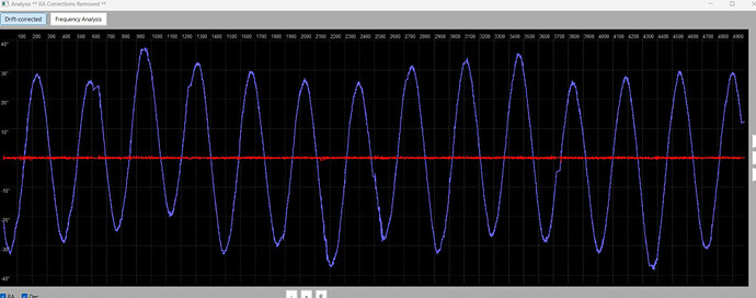
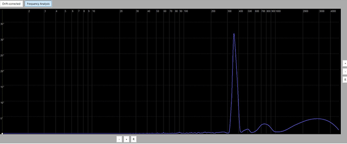
The main difference between the classic mounts with worm gears and the HD mounts, without going into the mechanics, is the lower weight of the HD mounts and that they do not need to be balanced. This makes them perfect for mobile use, as already mentioned. Unfortunately, compared to conventional mounts, strain wave mounts have a very high periodic gear error (PE), with a maximum usually between 20 - 60 arcseconds and a period between 300s - 600s. As an example, in Figure 1 you can see the PE curve of my WD-20 mount (Fig. 1), which shows a fairly clean sine wave (period length about 360s) and no higher harmonic oscillations in the frequency diagram (Fig. 2), nearly perfect… nearly.
Fig. 1: Periodic errors of a WarpAstron WD-20 mount with a 21 kg OTA load. Guide graph of a night with exposures of 600s. The partially visible steps are caused by dithering after each image.
Fig. 2: Frequency diagram of the periodic error from Fig. 1 with a main peak at F=361s. Harmonic oscillations at 1/2F, 1/3F, or 2/3F are not visible.
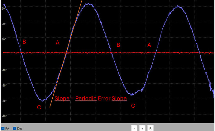
Without autoguiding these mounts cannot be used, as their tracking speed deviates by 0.3"/s - 0.6"/s and sometimes even more from the sidereal tracking speed (STS = 15"/s), resulting in star trail images. This maximum speed deviation can be read from (Fig. 3) as the maximum slope of the curve. In the example, it is about 0.6"/s. Please note that within a period of 360s (A to A), the mount runs twice 0.6"/s faster (points A) and once -0.6"/s (point B) slower than STS. At the maximum and minimum C, the mount runs almost perfect. The slope or speed of the mount changes considerably but over a relatively long period of time.
Fig. 3: Determination of the maximum slope, the maximum speed deviation of the mount’s movement from the optimal tracking speed.
Theoretically, according to common opinion, these errors can be nicely compensated by the autoguiding algorithms, as the change in speed happens very slowly, making the PE error very easy to correct. Unfortunately, this is not always the case, not very easy and very dependent on the parameters of the autoguiding algorithm.
Let’s take a closer look at the common theory.
A) Autoguiding, Guide Rate (GR), FPS Guiding
The constraints for all the following theoretical considerations are perfect seeing, no nocturnal animals bumping into the mount, wind gusts, etc. Assumptions in the following example: Framerate of the guiding camera (GC) = 1fps (1 frame per second), guide rate GR = 0.5x STS equals GR=7.5"/s (WarpAstron language: guide rate = pulse guide rate).
With these assumptions, how does guiding work when the mount is near point A (Fig.3) of the highest slope of the PE (with the highest speed ahead of STS)?
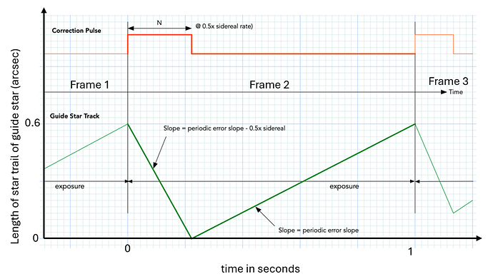
The movement of the guide star during autoguiding and the correction is shown in Fig. 4. At the end of the first frame the star position is estimated by the autoguiding algorithm, and the correction value K (in arcsec) is calculated. As result the mount is instructed to run slower for a time N = K/GR with GR=0.5x STS. In the example, the length of the correction pulse for an 0.6” error is only 50 ms (Note: in Fig. 4 this length is shown out of scale for better illustration).
Fig. 4: Sawtooth of the movement of the guide star in a x-t diagram (Extended Fig. 4.1 from (Chen)). Green is the movement of the guide star. Note: The pulse length is drawn much longer here for better illustration than the calculated 50 ms.
The guide star moves in phase A with a slope/speed of 0.6"/s in the 1s per frame by 0.6" away from the target point. Since the pulse length of the correction pulse is very short, 50 ms compared to the 1s per frame, the guide star is pushed back by the correction pulse in 50ms (the mount is not moving back but moves N seconds with -GR slower than STS). After the correction pulse it moves again with 0.6"/s ahead and is nearly back to 0.6" distance at the end of the second frame. This movement occurs in every frame and the star is oscillating between 0" and 0.6" from the target point. After 0.5 x F at point B, half the period, the slope is negative and the sawtooth flips to the negative side of the zero line. The guide star will oscillate between 0 and -0.6". This means that for an exposure with an exposure time close to, or greater, than 0.5xF, each star is imaged as a trail in the RA direction with a length of 2x 0.6" = 1.2"!
For the optimal guiding parameters this means:
-
Reducing the exposure time of a guiding frame by 50% (double fps) reduces the length of the star trail by 50%, halving the star trail length. The rms as a potential quality value is reduced by half!
-
Since this error is very large (1.2”), the guiding algorithm must react as quickly as possible. This means MinMo (Minimal Move), the value of the deviation of the star position in pixels at which autoguiding reacts/corrects, must be as small as possible. Theoretically, the aggression should be 100%, otherwise the correction pulse does not pull the star back to the zero line until the mount decelerates again (2nd derivative of the PE is acceleration).
The most important conclusion is to work with as many FPS as possible when autoguiding!
We would almost be at the end here, but the attentive reader will have already noticed that we made a crucial mistake. We assumed that the guiding algorithm takes the position of the star at the end of each frame as the position to calculate the correction pulse. We assumed that the guiding camera sees a point-like centroid, but this is not the case!
B) The incorrect correction of the autoguiding algorithm
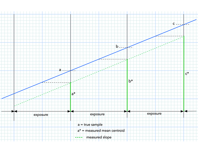
The guiding camera never sees a point-like star in phase A or B (Fig. 3), but in the example always a star trail of 0.6" length. The position of the centroid (which is a line) is taken as the mean or median value of the line, which is roughly the middle of the star trail not the end. Thus, in the example, the guiding algorithm will calculate the deviating position of the star not as 0.6" but as 0.3". The correction pulse will therefore correct only 0.3" at the beginning of the second frame and not 0.6" as we discussed initially. Thus, the star at the end of the second frame is not at 0.6" but at 0.9" distance (see also Fig. 5). The guide star moves from a to b, but the calculated correction value is a* and b*.
Fig. 5: Movement and position of the guide star in blue and the calculated star position and correction value on the dashed green line (Chen).
This is very bad because, theoretically, with this type of guiding (one-pulse-per-exposure paradigm), the guiding algorithm cannot catch up with the PE, as it calculates the wrong, much too small correction. It only manages to do so when the leading mount movement slows down again. However, we see the similar behavior at point B (Fig. 3) on the negative side of the target point. As a result, the actual star trail in the image is at least 1.5 - 2 times longer as previously assumed >1.8" - 2.4"! The rms value given by PHD2 is also calculated more than a factor of 0.5 too low! The rms value is wrong and only gives an indication of the image quality. With longer exposures over a full PE period, you might often see a double star like images because the sawtooth no longer returns to the zero line but oscillates distant to the zero line, above (phase A) and below (phase B). Every owner of a strain wave mount must be aware of this problem!
However, could this be improved or corrected in practice? One solution would be to adjust and change the position calculation of the autoguiding algorithms for this type of mount. Second, obviously, algorithms that recognize the PE slope and change the correction proactively are very helpful (as implemented in PHD2 as PPEC). Another simpler solution would be to set the guide rate (pulse guide rate in WarpAstron language) of the mount equal or at least nearly to the max PE slope (e.g., 0.6"/s) (~0.04x STS). Then the correction pulse would exactly eliminate the speed error within one guiding frame. The guiding camera would see a (nearly) point-like guide star at the end of the frame, resulting in correctly calculated error correction.
- Set the guide rate (pulse guide rate in WarpAstron language) as low as possible to optimize the calculation of the correction value.
Some readers will now say, but I see “round” stars, how can that be? My answer to that, besides a short focal length, large camera pixels, short exposure times, etc.:
C) Seeing is your best friend
This statement is sounds strange, but unfortunately, there is some truth to it. Seeing leads to irregularities in the position determination of the guide star and helps the autoguiding algorithm to correct more than theoretically possible by chance. Additionally, the stars are more smeared, and you no longer see the error in the image. Probably a reason why most users do not see some of the above-mentioned issues. The better the seeing and the better the image scale of the system (arcsec/pixel), the more likely you will see the errors. Of course, there is a balance point in practice. Here, everyone must find an optimum between seeing and FPS. The topic of aggression is also relevant here. The higher the aggression, the more susceptible the guiding is to oscillations, especially if the PE of the mount still has more harmonic oscillations.
D) OAG
An OAG does not bring any improvement in tracking accuracy with the described errors; it is irrelevant whether using a guide scope or an OAG, the max PE slope is an absolute error. The only advantage is that the image scale is larger, and the guiding algorithm can react faster.
That’s it for now. In some passages, I was a bit imprecise, but I wanted to present everything as understandably as possible. For those who like more formulas, please read the paper by Chen referenced at the beginning, which also discusses the theory of multi-star guiding. Once you understand the basic principle of autoguiding mounts with high PE, you can tune your guiding parameters in the right direction, and everyone must find their own golden point.
Another comment I can’t resist, forget about this RMS value from the guiding log. It is not a measure of good imaging; it only gives an indication of possible good imaging. Comparing RMS values is completely pointless with this type of mount.
At the very end… I love my WD-20! I found my balance point for the guiding parameters, even with using an AsiAir where I have no PPEC. It is high quality manufactured. There are not many harmonics like with other strain wave mounts, which make things even worse. If you follow some of the recommendations, you will have fun with it.
Clear skies
Markus
(I posted this in a German forum and referred to this already in the WarpAstron Discord channel)
